

Про проектування та застосування системи вимірювання температури датчика термопари
Залишити повідомлення
Як типовий елемент вимірювання температури, датчик термопари широко використовувався .
Далі є типова система вимірювання температури, керована одним мікрокомп'ютером Chip, яка складається з трьох частин: (1) схема підсилювача вимірювання; (2) ланцюг перетворення A/D; .
1. Дизайн обладнання
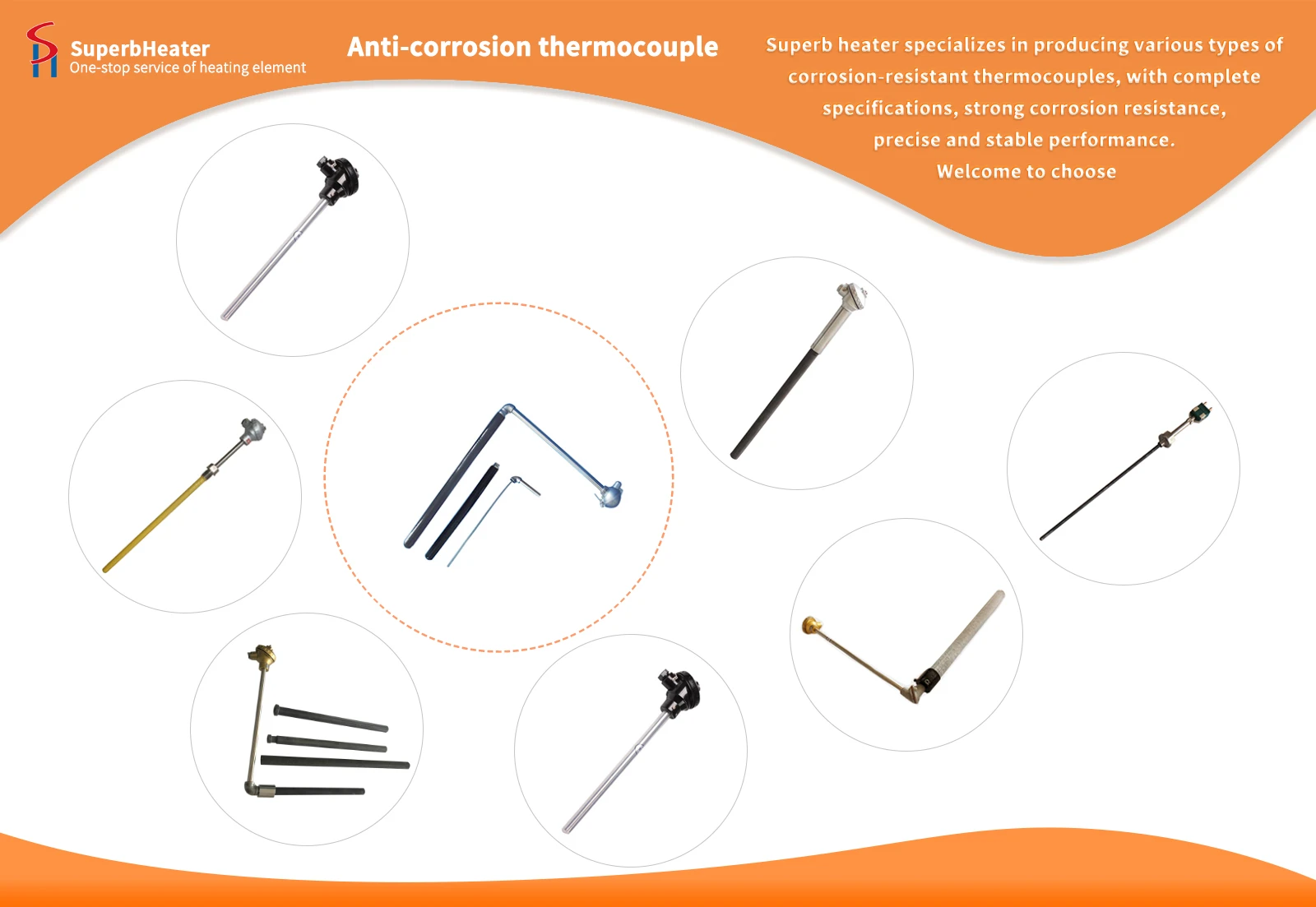
(1) Датчик температури термопари
This system uses nickel-chromium-nickel-silicon thermocouples. The measured temperature range is 0-655℃. The cold end compensation adopts the compensation bridge method. The potential generated by the unbalanced bridge is used to compensate for the change in thermoelectric potential caused by the change in the cold end temperature of the thermocouple. The unbalanced bridge consists of four bridge arms of resistors R1, R2, R3 (manganese copper wire winding), Rcu (copper wire winding) and a bridge voltage regulator, which are connected in series in the thermocouple circuit. Rcu and the cold end of the thermocouple are at ±0℃, and R1=R2=R3=1Ω. The bridge power supply voltage is 4V, powered by a voltage-stabilized power supply. Rs is a current-limiting resistor, and its resistance value varies with different thermocouples. The bridge is usually balanced at 20 ступінь . У цей час чотири опори мосту мосту мосту - r 1= r 2= r 3= rcu, і немає виходу на кінці a і b ., коли холодна кінцева температура відхиляється від 20 градусів, наприклад, коли він зростає, rcu -lenderes Термопара зменшується у міру збільшення температури холодного кінця . UAB дорівнює зниженню термоелектричного потенціалу, а вихідний потенціал залишається незмінним після того, як UAB накладається на термоелектричний потенціал, тим самим досягаючи автоматичного завершення компенсації холодного кінця .}}}}
(2) Схема підсилювача вимірювання
У фактичних схемах вихід сигналу з термопари - це не більше кількох десятків мілівольтів (<30mV), and contains common-mode interference such as power frequency, static electricity and magnetic coupling. To amplify this kind of circuit, the amplifier circuit needs to have a high common-mode rejection ratio, high gain, low noise and high input impedance. Therefore, a measurement amplifier circuit is suitable. The measurement amplifier is also called a data amplifier, instrument amplifier and bridge amplifier. It has a high input impedance and is easy to match with various signal sources. Its input offset voltage, input offset current and input bias current are small, and the temperature drift is small. Due to the small time temperature drift, the measurement amplifier has good stability. The measurement amplifier is composed of three op amps, and the differential input terminals R1 and R2 are connected to the in-phase terminals of A1 and A2 respectively. The input impedance is very high, a symmetrical circuit structure is used, and the measured signal is directly added to the input terminal, thereby ensuring a strong ability to suppress common-mode signals. A3 is actually a differential follower, and its gain is approximately 1. The gain of the measuring amplifier is: AV=V0/(V2-V1), AV=Rf/R(1+(Rf1+Rf2)/RW). In this circuit, as long as the performance of op amps A1 and A2 is symmetrical (mainly referring to input impedance and voltage gain), their drift will be greatly reduced. They have high input impedance and common mode rejection ratio, are very sensitive to tiny differential mode voltage, and are suitable for measuring signals transmitted over long distances. Therefore, they are very easy to use with sensors with tiny outputs. RW is an external resistor used to adjust the gain, and a multi-turn potentiometer is used here.
У фактичній схемі A1 і A2 використовують низькосхилі, високоточні чіпи OP AMP OP -07, чиї вхідні вхідні зміщення температури температури дрейфу і вхідне зміщення поточного дрейфу температури IIOS дуже невеликий . op -07 використовує технологію Ultra-High та ii-mingle, а також-це і iios, і ii-vidos-це і is videly-це не мала використовується в стабільній інтеграції, точній додаванні, виявленні порівняння та точній ампліфікації слабких сигналів . op -07 вимагає подвійного джерела живлення, а діапазон робочої температури {0-70 градус ., як правило, нульове регулювання не потрібно ., якщо належне коригування. A3 uses 741 chip, which requires dual power supply, and the power supply range is ±(3-18)V. The typical power supply is ±15V, which should generally be greater than or equal to ±5V. It contains compensation capacitors inside, and no external compensation capacitors are required.
(3) конверсія A/D (аналого-цифрова)
Сигнал напруги, посилений підсилювачем вимірювання, має діапазон напруги 0-5 v . Цей сигнал є аналоговим сигналом і не може бути прийнятий за допомогою комп'ютера, тому конверсія A/D повинна бути виконана . у фактичній схемі, мікросхема Icl7109 є виборним. icl7109, що має високий рівень, low-drift, low-cost dual-integral 12-bit A/D converter. Since the current 12-bit successive approximation A/D converter is relatively expensive, the cheap dual-integral 12-bit A/D converter ICL7109 can be used in situations where the speed is not too high, such as in high-precision measurement systems Для різних сенсорних сигналів, таких як зважування, вимірювання тиску та вимірювання температури .
Завдяки наведеному вище аналізі системи вимірювання температури датчика термопари, я сподіваюся, що це буде корисно для роботи кожного та вивчення .